How NASA Reinvented the Rocket Engine
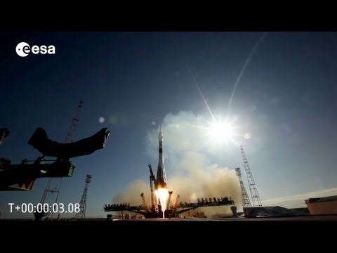
This is no ordinary rocket engine. Limited by the technology of their times engineers and physicists have theorized this propulsion method for centuries, but the constraints of time may have just lifted with NASA’s revolutionary test of this rotating detonation engine in January 2023. With the very latest advances in material science and computational fluid dynamics, NASA has managed to break through to test a 3D printed rocket engine that could improve fuel efficiencies of rockets by up to 5%. [1] A 5% improvement in fuel efficiency for a rocket engine is not a marginal gain. Rocket weights are dominated by fuel. The 1st stage Saturn V had a dry mass of 137,000 kilograms, when fully loaded with propellant its weight was 2.2 million kilograms. The first stage was 94% fuel. A 5% increase in fuel efficiency represents a 103 tonne decrease in fuel. That’s not far off the total dry weight of the Falcon 9 rocket. [2] This does not just provide cost savings. It represents a drastic change in capabilities of rockets. Allowing humans to launch larger payloads further into the solar system. This latest test of the technology saw the engine run 18 times, with a maximum firing duration of 113s seconds per run. [3] This was a test, and the engine is not ready to use, but this test represents the culmination of decades of research, enabled by newly developed metals and manufacturing techniques and the very latest advances in computational fluid dynamic modeling. Let’s delve into the science and engineering behind Rotating detonation engines to see how they work. Engines powered by detonations are not a new concept. The Air Force Research Laboratory developed this heavily modified Rutan Long EZ. Powered by 4 tubes in which the detonations occurred. Traditional rocket engines work by mixing fuel and an oxidizer, using a continuous igniter. With the ignitor typically located at the top of the combustion chamber, a flame front needs to travel through the fuel mixture to complete combustion. If the speed of this flame front is below supersonic speed, the combustion is called deflagration. If the “flame front” travels through the mixture at over Mach 1, then the process is called detonation. Almost all combustion engines work with deflagrations, but as their name implies Rotating detonation engines use a supersonic flame front to produce thrust, and as a result can produce more thrust for the same volume of fuel. However, this is easier said than done. The energy needed to initiate a detonation is very large, and for these pulsed detonation engines used on the Air Forces test vehicle, the detonations needed to happen hundreds of times a second. We can initiate a normal deflagration combustion flame front, which travels along the tube and with some encouragement will transition to a detonation, but the causes of this aren’t totally understood and are not always reliably repeatable. We know that detonations happen more often when the fuel is turbulent so to create these conditions, pulsed detonation engines often include physical barriers. One method to achieve this is by placing a spiral inside the tube. [4] Pulsed detonation has a more obvious problem. They don’t provide constant thrust. They pulse. Rotating detonation engines are the solution to both of these problems. They consist of a ring shaped combustion chamber. The process starts by opening a valve at one end of a tube and letting a fuel mixture fill the tube. The valve closes and an ignition source at the closed section goes off and the detonation begins. A shockwave begins to travel around the circumference of the ring that increases the pressure and temperature of the gas behind it almost instantaneously. This gas then expands and leaves the tube at extremely high velocity, creating thrust. This cycle then repeats with the shockwave traveling in a never ending circle. This clever arrangement solves the major problems with pulsed detonation engines by having to only set off the detonation once, it eliminates the unreliability of setting off thousands of detonations a second and its continual spiral around the combustion chamber results in consistent thrust. Keep in mind these detonation fronts are going FAST, operating at Mach 3-6 depending on the fuel mixture. This means that the waves complete a full circle in a thousandth of a second, with operating ranges between 1 to 10 kHz [5]. This is an incredibly difficult phenomenon to harness. Detonations release energy very quickly, are hard to control, and are unstable by nature. In fact, for the last century of aerospace advancement, engineers have been working very hard to prevent detonations in their rocket nozzles. During the development of the F1 engine in the Apollo program, the engineers struggled to control what they called “thermodynamic instabilities”. These were in fact detonations that were destroying the engine.[6] On June 28th 1962 these combustion instabilities caused an engine to be completely destroyed during testing. This problem was plaguing the engineers of the Saturn V and is arguably the greatest challenge they faced in scaling this monstrous rocket to reach the moon. A list of 18 potential sources of the instability were made. This was an incredibly complex and dynamic problem. One method to reduce instabilities and to prevent pressure waves from amplifying off the side walls, like a sound wave, was to install baffles that separated the combustion chamber radially. Several iterations of baffles were designed, but with no computational method available the engineers of the F1 engine turned to the next best practical method. They set off tiny bombs inside the combustion chamber during operation to quickly induce small combustion instabilities. The combustion chamber bomb was attached to the injector plate with the detonator inside the combustion zone. The detonator was encased in nylon that would ablate away in the heat of combustion over time, allowing the engine to reach full operation before detonating. Resulting in a pressure wave that traveled through the engine just as a combustion instability would. The engineers could test the effectiveness of new baffle designs by timing how long it took for normal operation to resume after the detonation. These baffles effectively acted as acoustic dampeners, like the foam wedges we place in sound treated rooms. For decades engineers have been working to prevent these uncontrollable dynamic detonations. But engineers and scientists are stubborn kinds of people. When they hear “uncontrollable” all they hear is “not yet controlled”. And rotating detonation engines effectively use the exact phenomenon that these baffles were trying to prevent, allowing a traveling shockwave to travel tangentially around a ring shaped combustion chamber. The appeal of using detonations as a combustion and propulsion mechanism is precisely what makes them dangerous, their quick release of energy. We can visualize the amount of energy we can extract by comparing the combustion cycle of a hypothetical detonation engine and a normal gas turbine engine on a pressure-volume chart. This chart simply plots the pressure and volume of air as it travels through an engine. In a gas turbine, the air enters the engine at this pressure and volume. A compressor decreases its volume at a constant pressure. It then moves to the combustor where heat is added in at a constant pressure. Then the gas passes through a turbine as it expands until it reaches its initial condition. The energy we extracted can be found by finding the area enclosed by these curves. In a detonation cycle we skip the combustor stage completely, and instead the detonation wave increases the pressure of the gas almost instantaneously. Spiking it much higher. This creates a much larger area inside the curves. The theoretical differences in thermodynamic efficiencies using this analysis method are immense. Using hydrogen as our gas, a gas turbine engine has a thermodynamic efficiency of 36.9% while a detonation engine has a thermodynamic efficiency of 59.3%.[5]. Simply, this means that more energy is extracted from the same amount of fuel. However, an increase in energy yield is of no use to us if we can’t control it, or it simply destroys our engine. To harness his energy we needed to develop new materials and manufacturing techniques. This is where a new material, specially developed for metallic 3D printing comes into play. Data sheet on table GRCOP-42. A nasa developed alloy made up of niobium, chromium and copper. A high strength metal alloy specially formulated to not only have a very high melting point, but a high thermal conductivity. Meaning it takes more energy to melt it and it conducts the energy away more efficiently to prevent itself from melting, and critically, NASA has more recently developed a method of using it metallic 3D printing, meaning we can create incredibly complex geometries with this new age material. Maintaining this reaction is incredibly difficult. The shockwave, by nature, is traveling incredibly fast, and causes rapid changes of temperature and pressure. Take the injectors. They have to be designed to handle not only high flow rates but also drastic changes in pressure and temperature. As the shockwave travels by condition change from 0.01 Megapascals of pressure at 300 kelvin, to 2 megapascals of pressure and 3000 kelvin. That cycle happens one thousand times per second.[7] Our copper based alloy can help us dissipate that energy, but these inlets need to switch from injecting gas to resisting the pressure of the shockwave in milliseconds. To manufacture an inlet capable of handling these conditions the engineers needed 3D printing. A typically machined injector may look something like this, but the designers of the rotating detonation engine need to handle back flow, and for this they can turn to fluid diodes, which would be impossible to manufacture with traditional cutting tools. The shape of this passage allows fuel to flow easily in one direction, but when flow attempts to travel in the opposite direction it impinges itself, resisting flow. Effectively it’s a valve with no moving parts. A perfect solution for this application. [8] The use of metal 3d printing doesn’t stop at inlet design. Every part of the rotating detonation engine requires delicate shaping to harness the power of detonation. From the combustion chamber design to ensure the shockwave remains in rotating to the tiny cooling channels running through its walls. The rotating detonation engine that NASA developed used a 3D-printed thrust chamber that was actively cooled using Deionized water.[3] It also features an aerospike nozzle. Aerospike nozzles are kinda like inside-out nozzles. Instead of the traditional bell shaped nozzle, it features a cone at the center of the exhaust. Aerospike nozzles allow the rocket to operate more efficiently at a range of altitudes. To understand why, we need to cover some basics of nozzle design. The bell nozzle operates optimally at a certain external atmospheric pressure. To work at its most efficient we want the exhaust pressure at the nozzle exit to equal the external atmospheric pressure. If the external pressure is higher than the exhaust exit pressure we are operating in the overexpanded condition. Flow separation from the nozzle occurs and energy is lost. If the external pressure is lower than the exhaust exit pressure we are operating in the underexpanded condition, the gas expands outwards outside of the nozzle and energy is lost. However if we match the exit pressure and atmospheric pressure neither happens and exhaust velocity is maximized, making our engine more efficient. We could fit rockets with variable geometry nozzles like fighter jets, but this would add a lot of weight, complexity and cost. These nozzles are a lot bigger than fighter jets and until very recently were single use. [9] Aerospikes provide a lighter simpler alternative to variable geometry exhausts. Here the shape of the exhaust is dictated by the external atmospheric pressure. At higher pressures, at lower altitudes, the exhaust is compressed against the aerospike, which redirects the exhaust to point straight down. No flow separation can occur as the pressure is pushing it against the aerospike. As pressure lowers this expansion continues, and the aerospike automatically compensates to external pressure changes. The exact science of these aerospike nozzles is a lot more complicated than this and deserve a video entirely dedicated to them alone. But they are uniquely suited to rotating detonation engines, as an aerospike engine, with this cone design, requires a circular combustion chamber, which the rotating detonation engine also requires. However these is a more important reason, to optimize the design of a bell nozzle we need a consistent chamber pressure in order to optimize our expansion ratio, with the rotating detonation engine the chamber pressure is constantly changing along the circumference of the combustion chamber. The aerospike’s ability to adapt to external atmospheric pressures also helps it adapt to internal chamber pressure changes. [10] There is a lot more to do to make rotating detonation engines viable. These prototypes, while promising, struggle to run for long enough to produce prolonged thrust. In 2021, Japan tested a rotating detonation engine in space, which operated for 6 seconds, producing 500 Newtons of thrust, and while this was a proof of concept it’s a long way from the millions of Newtons traditional rocket engines can achieve.[11] The mechanics of detonations are still not understood fully. This means that maintaining a stable detonation front is extremely difficult. The system is inherently chaotic. Engineers are fighting against entropy to control these powerful turbulent flow regimes. With each revolution of the shockwave more chaos is introduced to the system. A single vortex on revolution one can cause a ripple effect until the rotation becomes completely unstable by rotation 20. NASA even stated that their tests sometimes fluctuate from have 2 to 5 co-rotating detonation waves in the combustion chamber at once.[12] This NASA test was a huge milestone for the technology. They demonstrated that their copper based 3D printed material could survive for long enough in this environment with their longest run lasting nearly 2 minutes, and they managed to successfully initiate the detonation front multiple times with 17 restarts over 600 seconds. The biggest challenge facing engineers of rotating detonation engines is creating flow models to predict these instabilities and developing methods to dampen and control these combustion instabilities, just as the engineers of the Apollo program did all the way back in the 1960s. The next real engineering video is ready right now. It’s about the M1 Abrams. We detail it’s unique turbine engine, an engine type typically used in aircraft, but used in this heavy armored vehicle for 2 special reasons. We dig into how the armor of the M1 has evolved over the past 4 decades and how it works. It will be available on YouTube in 2 weeks, but you can watch it now, before anyone else on Nebula, as a thank you to our show’s supporters. Here’s a rapid fire list of incredible features you can enjoy for the low cost of just 2 dollars 50 a month. Ad free videos Early access before anyone on YouTube Exclusive behind the scenes of our documentaries, like these 2 uncut interviews from our Helion Documentary Exclusive classes and originals from me and all your favorite creators. I know they are your favorite, because it tells me what channels my viewers watch in my analytics. We got Mustard, Wendover Productions, Practical Engineering, the list goes on. And here’s the incredible thing , by signing up with my link you aren’t just supporting me. You are supporting educational creators across the board, because we all own a percentage of this platform. We created it to give us creative freedom, and we have achieved it. Nebula is the lifeblood of our channel. As sponsors and ad revenues have dropped off lately, Nebula is what is ensuring our incredible team of writers, animators and editors across Real Engineering and Real Science, including myself, can feel secure in uncertain financial times, and that’s thanks to you. Real Engineering started with just me. I barely knew how to animate. I just had a dream of recreating the magic I felt watching nature documentaries on TV growing up, but for engineering. Over the past 6 years I have continually reinvested revenue to hire the incredible people that make this channel possible. Mike, Dylan, Stephanie, Eli, Kirtan, Lorraine, Josi, Graham. This channel is not just me. It’s a group of dedicated people that you, our viewers, employ. If you want to see Real Engineering continue to evolve and increase in production value, this is how you support that mission. 2 dollars 50 a month for the annual plan, and you get all that incredible content to boot.